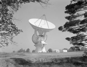
When the 140-foot (43-meter) telescope was completed in Green Bank, West Virginia in 1965, it was the epitome of engineering innovation. It stands 200 feet tall and weighs 8200 tons. To this day, no other polar-aligned telescope of its huge size exists anywhere else in the world.
Gem in the Rough
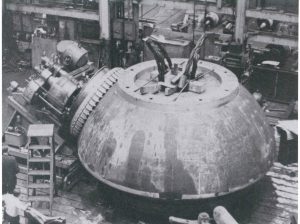
This 17.5-foot hemispherical piece is the structural heart of the 140-foot (43-meter) telescope in Green Bank, West Virginia. It supports the full rotating weight of 2700 tons on the .005-inch thick oil film between it and the main hydrostatic pad supports. Cast by General Steel Industries, it weighs in excess of 150 tons– one of the largest steel castings ever poured, certainly the largest ever cast of 3.5% nickel. Its size was limited by the small country railways and tunnels between its casting site in Eddystone, Pennsylvania and the Green Bank site.
Mimicking the Earth’s Axis
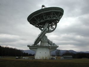
The 140-foot telescope in Green Bank, West Virginia is the largest equatorially-mounted telescope in the world. That means that it moves on a gear parallel to the equator of the Earth because it spins on an axis aligned to that of the Earth. In this photo, its two axes of motion are in view. One is the giant white semi-circular tube with just-visible toothy gears around its edge. This gear is driven by the polar shaft which is aligned to the axis of the Earth (the white shaft braced at the right end of the deck and aiming up at an angle pointing to about 10 o’clock). When the Earth turns, this axis turns in the opposite way, to keep the 43-meter dish aimed on the sky. The tilting gear is the wedge shape under the dish’s support structure.
Prime Focus of the 140-foot
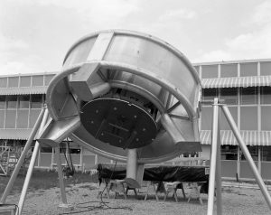
Sitting 60 feet above the dish of the 140-foot telescope was this original feed ring. Radio waves bouncing from the 43-meter parabolic dish came to a focus directly where the receiver would have been placed, inside the black cartridge of this ring.
New Digs at the 140-foot
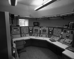
In 1972, the control room of the 140-foot (43-meter) telescope in Green Bank, West Virginia got an upgrade. Gone were the Flash Gordon-looking analog monitors and dials and in their place was this suite of Honeywell 316 computer modules. It had 32 Kb of memory, a card reader for program loading, CRT displays, and a position panel which controlled the telescope’s position, errors, and slew rates. These days, the telescope can be run remotely from the Jansky Lab up the lane or from a laptop stashed in a cabinet in this room.
Anechoic Chamber
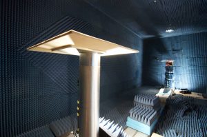
Manmade radio signals (from wireless devices, orbiting satellites, spark plugs, microwave ovens, etc.) swamp the weak waves we detect from objects out in space. Before we install any piece of equipment in Green Bank, we test it in this special room called an anechoic chamber. The pedestal in the foreground holds the device to be tested, and an antenna at the back of the room picks up its radio waves, if any. The foam cones covering walls, floors, and ceilings break up radio waves that are not in direct line with the antenna. Any radio-leaking electronics are encased before they are brought close to the telescopes.


